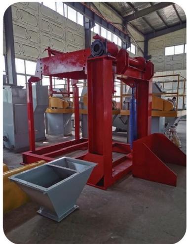
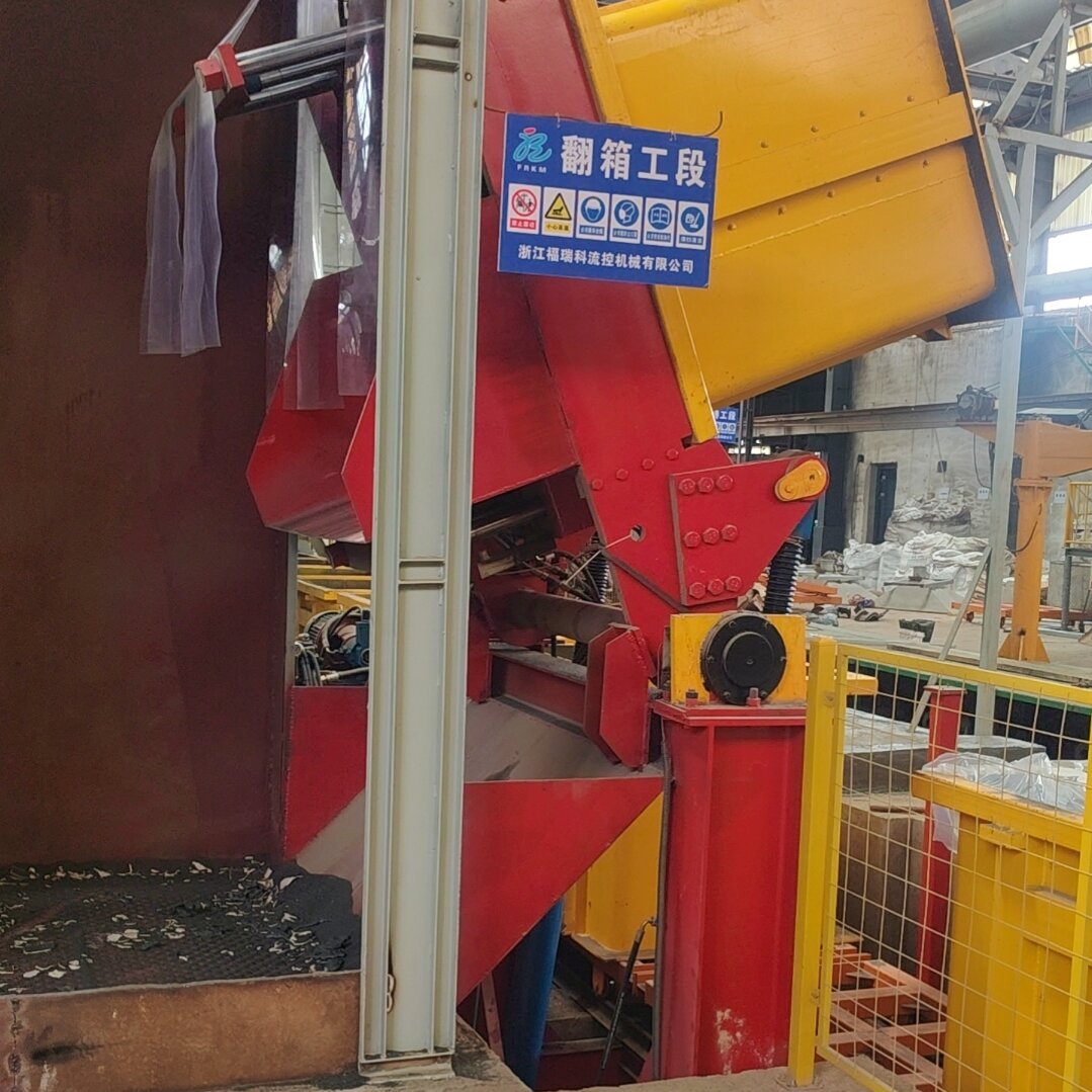
1.This Hydraulic turnover machine is applicable to automatic and semi-automatic production lines in the foundry industry, and is designed to transfer castings to the next station.
2.The tilting capacity of this machine ranges from 10 to 30 tons. It can tilt the sand box (including castings and sand) weighing 10–30 tons backward by 126 degrees.
The initial positions of the two types of oil cylinders are as follows: the two oil cylinders with a diameter of 63 mm are at the starting position, and the oil cylinder with a diameter of 180 mm is at the starting position. The working sequence is carried out in the following order:
1.The two oil cylinders with a diameter of 63 mm simultaneously move from the starting position to the end position (until the sand box base is clamped), completing the clamping action of the sand box base.
2.The oil cylinder with a diameter of 180 mm moves upward to the end limit position. The tilting frame of the turnover machine drives the sand box to flip, completing the box tilting action.
1.Turn on the main power switch and place the sand box at the designated position of the Hydraulic turnover machine.
2.Press the hydraulic pump start button, then press the clamping cylinder button to lock the sand box base.
3.Press the upper pressing cylinder button to compress the sand box.
4.Press the main cylinder lift button to push the sand box upward and rotate it by 126 degrees.
5.Press the main cylinder retract button to return the sand box to its original position.
6.Press the upper cylinder release button to loosen the sand box, then press the clamping release button to unlock the base.
7.Push the sand box away to complete one tilting cycle.
Automatic Mode: Press the auto button; the tilting action follows the same sequence as above. After one automatic tilting cycle is completed, a time delay will be activated. The next tilting cycle must be initiated within the delay period; otherwise, the machine must be shut down for reset.
1.Daily Maintenance (Per Shift)
2.Special Maintenance Requirements
3.The hydraulic station should be installed in a location with low dust, small temperature difference between winter and summer, and minimal impact from vibration and heat generated by other equipment.
4.The directional valve manifold should be installed close to the oil cylinders.
5.Wear-resistant hydraulic oil is generally adopted for this system (L-HM 46 for summer, L-HM 32 for winter). If the ambient temperature is too low in winter, run the machine idling for a period of time until the oil temperature rises before formal operation.
6.Before startup, carefully check the power supply voltage and the rotation direction of the oil pump. Start the machine under the conditions that the electromagnetic directional valve is in the neutral position, the hydraulic cylinder is unloaded, and the system is depressurized. During the air bleeding of pipelines and hydraulic cylinders, a layer of white bubbles will float on the oil surface of the fuel tank. If the bubbles cannot be eliminated for a long time, stop the machine immediately and restart after the bubbles disappear. After idling for a certain period, operate the machine according to the set working conditions; increase the pressure gradually from low to high, and the set pressure shall not exceed the rated pressure.
7.Working Fluid Inspection: Take samples from the upper, middle and lower layers of the fuel tank respectively to check the cleanliness, water content and viscosity. Replace the fluid if it fails to meet the standard requirements.
8.Cooler: The cooler adopts water cooling, with the front nozzle connected to cooling water. Regularly check the pipe joints and screws for looseness.
9.Control Valve Inspection: Check the pressure setting value of the relief valve, the dynamic performance of the solenoid valve of the pressure regulating mechanism, and the neutral position leakage of the valve. Replace the valve if its performance drops significantly.


 Send Email
 售前客服
售前客服